What is PuzzleUrPrint supposed to do?
The "PuzzleUrPrint"-Addon generates connector placeholders which are used to dissect mesh objects into separate parts for 3D Printing. The resulting connectors help to assemble the pieces after 3D printing without needing glue. This solves some typical problems found with 3D-Printing. Especially, that 3D-Printers are "always too small". Already, objects with more than 25x25x25cm are to big for most 3D Printers. This addon allows to disect every object in to smaller pieces in printer size. Moreover, this also allows to create 3D-prints with moveable parts. For example, an action figure can get moving arms by separting the arms and using a cylinder shape as connector.
Similarly, the addon can also produce dovetail constructions allowing to slide two pieces together and have a stoper fix them in position. This way for example, you can produce a wall mount with hidden screws, or fixate large.
Last but not least the addon also allows to produce (3D)-jigsawpuzzles. This is a great source for christmas presents until eternity.
Install
- install by File/User Preferences.../Addons/Install from File/
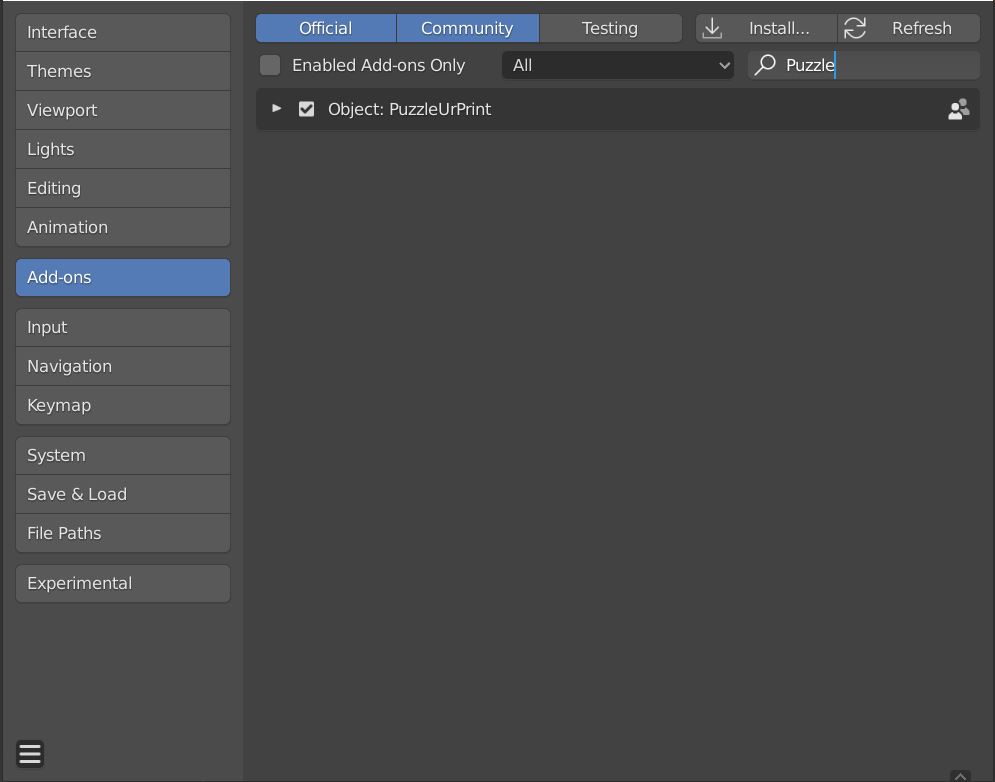
Install Add-on from the zip-File and check the checkbox.
In Blender open the "Edit"-dropdown menu. Choose "Preferences...". In the side bar click on Add-ons. Click on "Install..." at the top of the window. Locate the "PUrP_*V*.zip" on your computer and double click or click "Install Addon" in the bottom of the window. Check the check box next to "Puzzle Ur Print". In order to have the "Puzzle Ur Print" by loaded on default with Blender click "Save User Settings" under the Hamburgermenu in the left bottom corner and exit User Preferences. The "Puzzle Ur Print" Panel will now appear in the right side panel (n-panel) of the 3D-Viewport.
Connectors
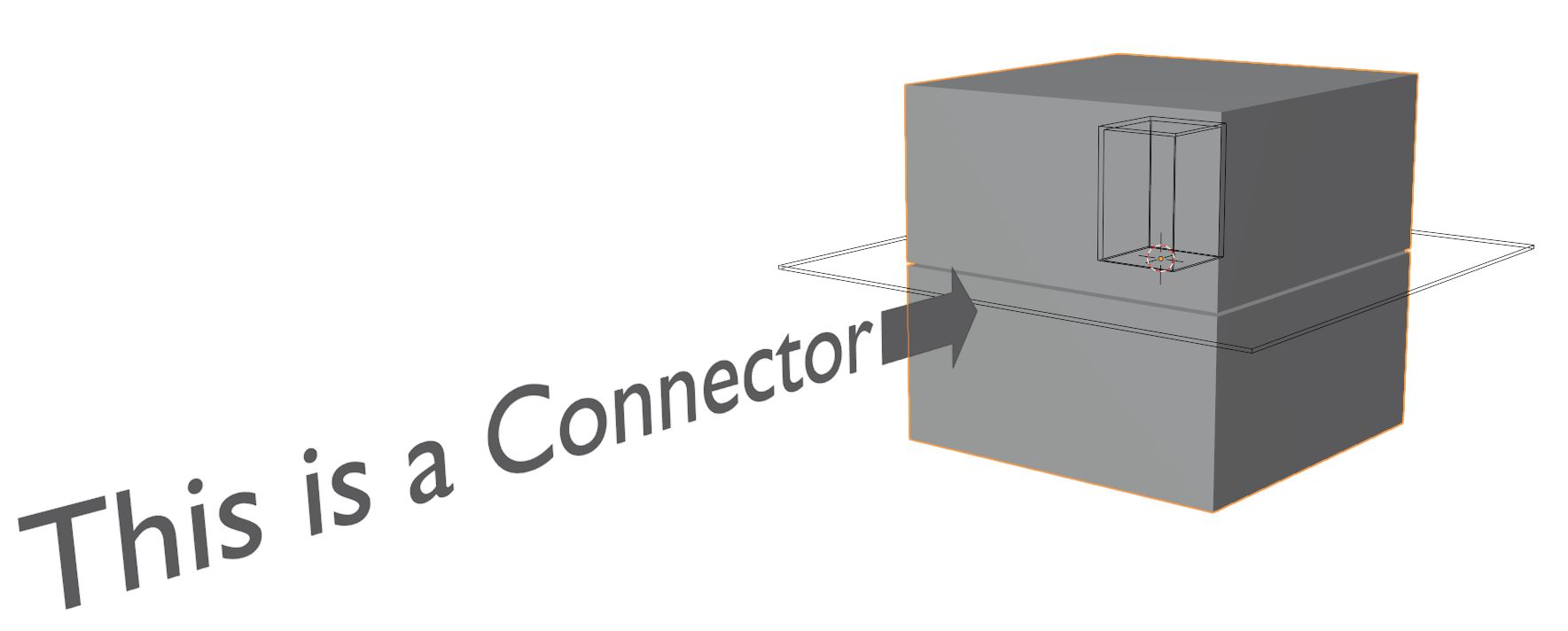
The addon helps to cut models in pieces and simultansouly add connectors for simple reassambling after 3D Printing. The PuzzleUrPrint-addon can produce a broad variety of these Connector called objects (or combination of objects), which are internally used in boolean operation to eventually generate the transformation intended. Here you see a cube with a 'Single Connector' in male-female configuration with cube as Inlay type.... Lets see how it looks after applying.
After Applying
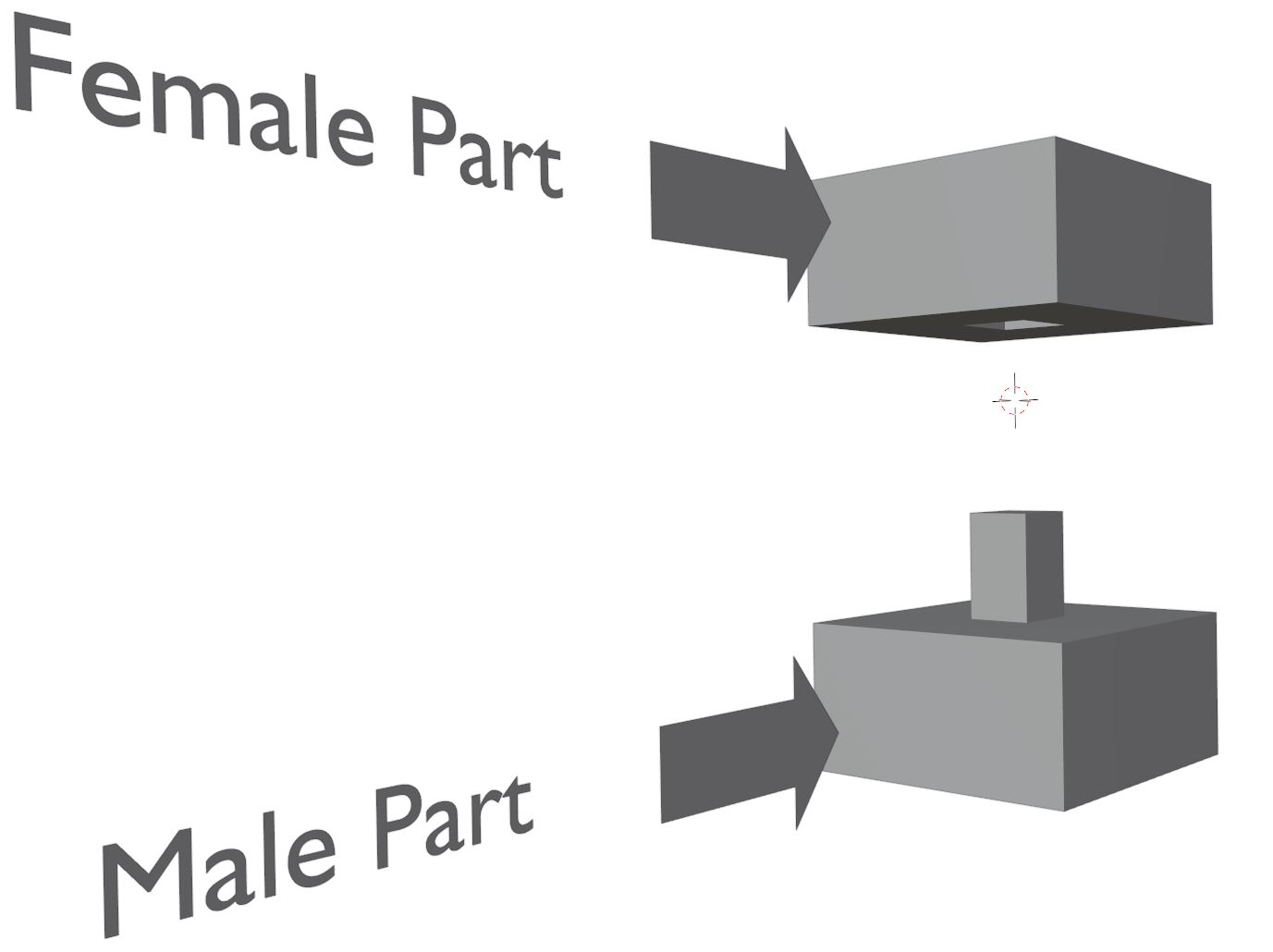
This is the result you would get when you apply the connector from the last slide to the cube. The cube is now cut in half. Moreover, the bottom part has a male connector attached while the top part has a hole in the shape of the connector. If you would print that you could put both parts together again easily. This can be helpful for many things.
- Print large: 3D-printers are typically very small. Use the addon to desect large models into printable bits. Your lifesized Koro is only a few clicks and days of printing away (support cloud.blender.org!!)
- Add Functionality: Using cylinders as Inlays allows to turn parts against each other. A 'joint'-cut allows to make maken even more delicate joints. Print your own actionfigures, monsters, sculptures,... with movable parts.
- Puzzles: Of course you can make puzzles with PuzzleUrPrint. Whether you deform a plane (with some thickness of course) and make a more tradition 2D puzzle, you can also make 3D Puzzles by disecting larger objects for a new generation of challenging puzzles Sculpt your and print it. it'll change the whole experience.
- Wallholders and Fixation: You can add dovetail and other shapes to make objects slide into each other and if you like stop at the right point. This is ideal for wallholders and nice to hide the screws.
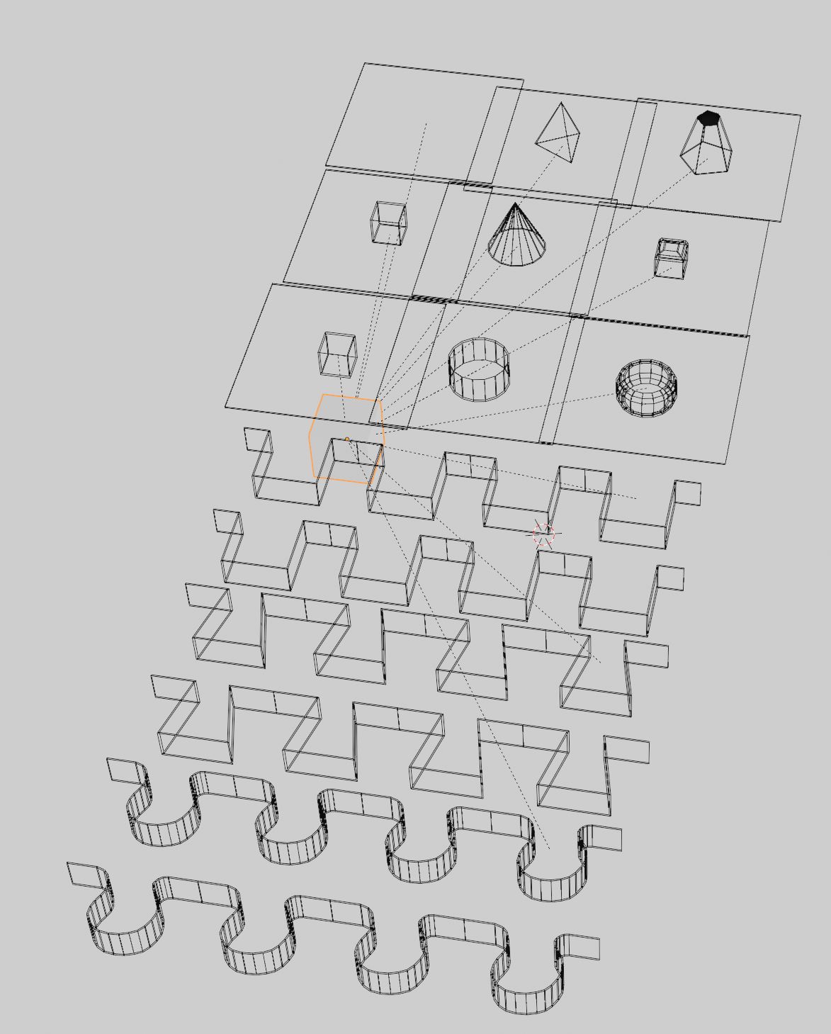
Many Connectors shapes: The Settings
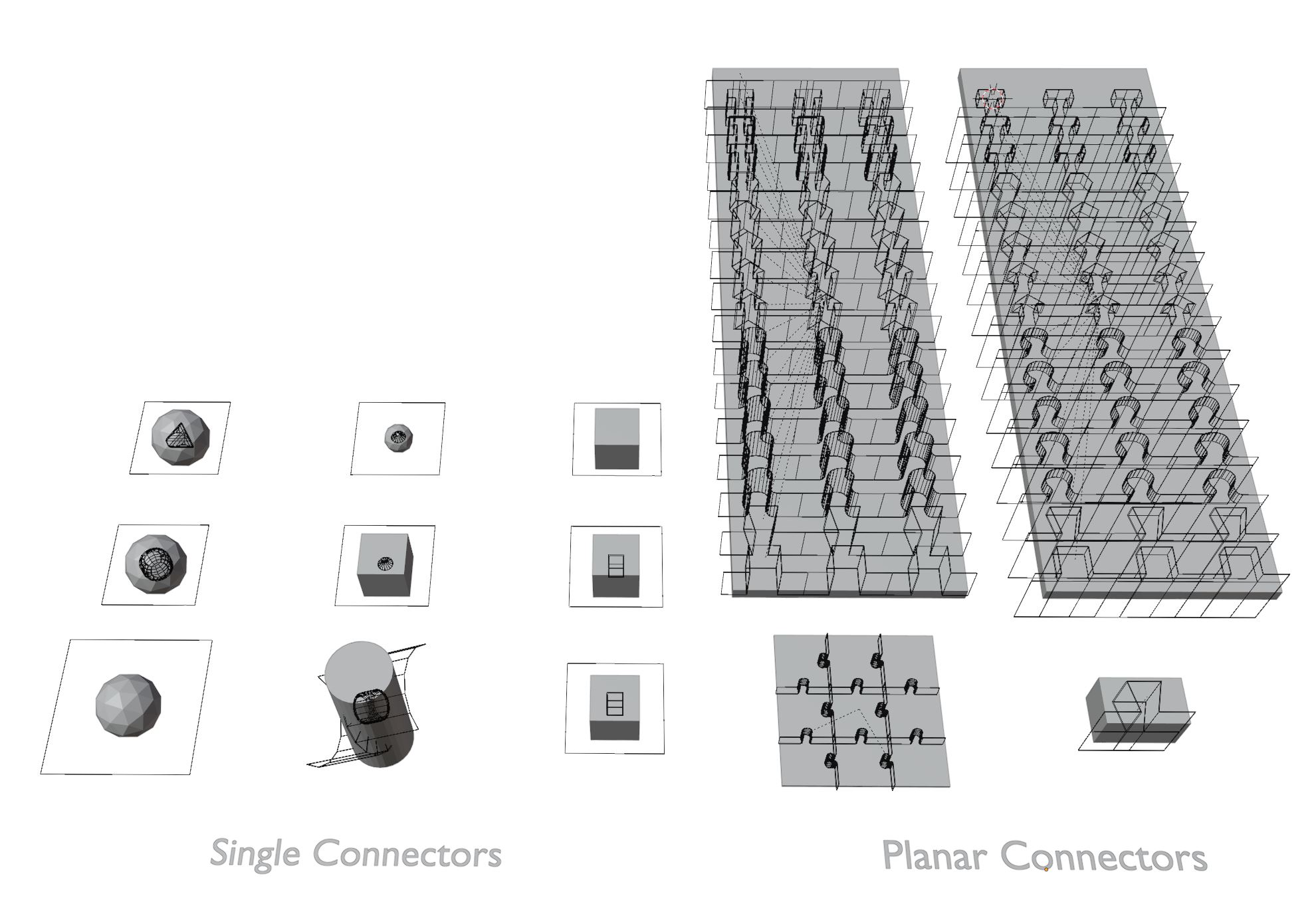
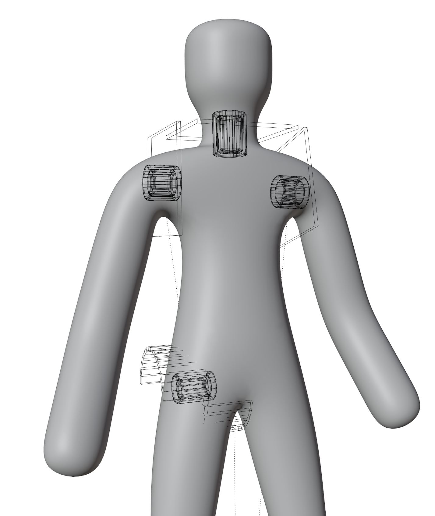
Here you see a couple of examples of connectors. They can have all kinds of shapes and produce different functionalities. Quite diverse, right? You can produce all of these connectors by adjusting the settings in the 'Add, Exchange, Apply'-dropdown. With 'Add Connector' a new connector will be born using the current settings in the 'Add, Exchange, Apply'-dropdown. If you haven't specified another (mesh) object by selecting it or another connector is selected, the addon will try to map (something like parenting) the connector to the last known 'Center Object'. This is the object set in the top line in 'Add,Exhange,Apply'.You can change the settings via the 'Add, Exchange, Apply'-dropdown or via the gizmos visible when a connector is selected. While changing settings via gizmos will take immediate effect on the mesh or the settings in the dropdown, changes in the 'Add, Exchange, Apply'-dropdown will only take effect after pressing the 'Exchange'-Button. If you are interested to know which settings produced a specific connector, select the connector of interest and press 'Active to Settings' in the 'Add, Exchange, Apply'-dropdown. The dropdown now shows the settings of the active connector. You can 'paste' these new settings onto an existing connector by selecting it and pressing 'Exchange'.
Initialize PuzzleUrPrint
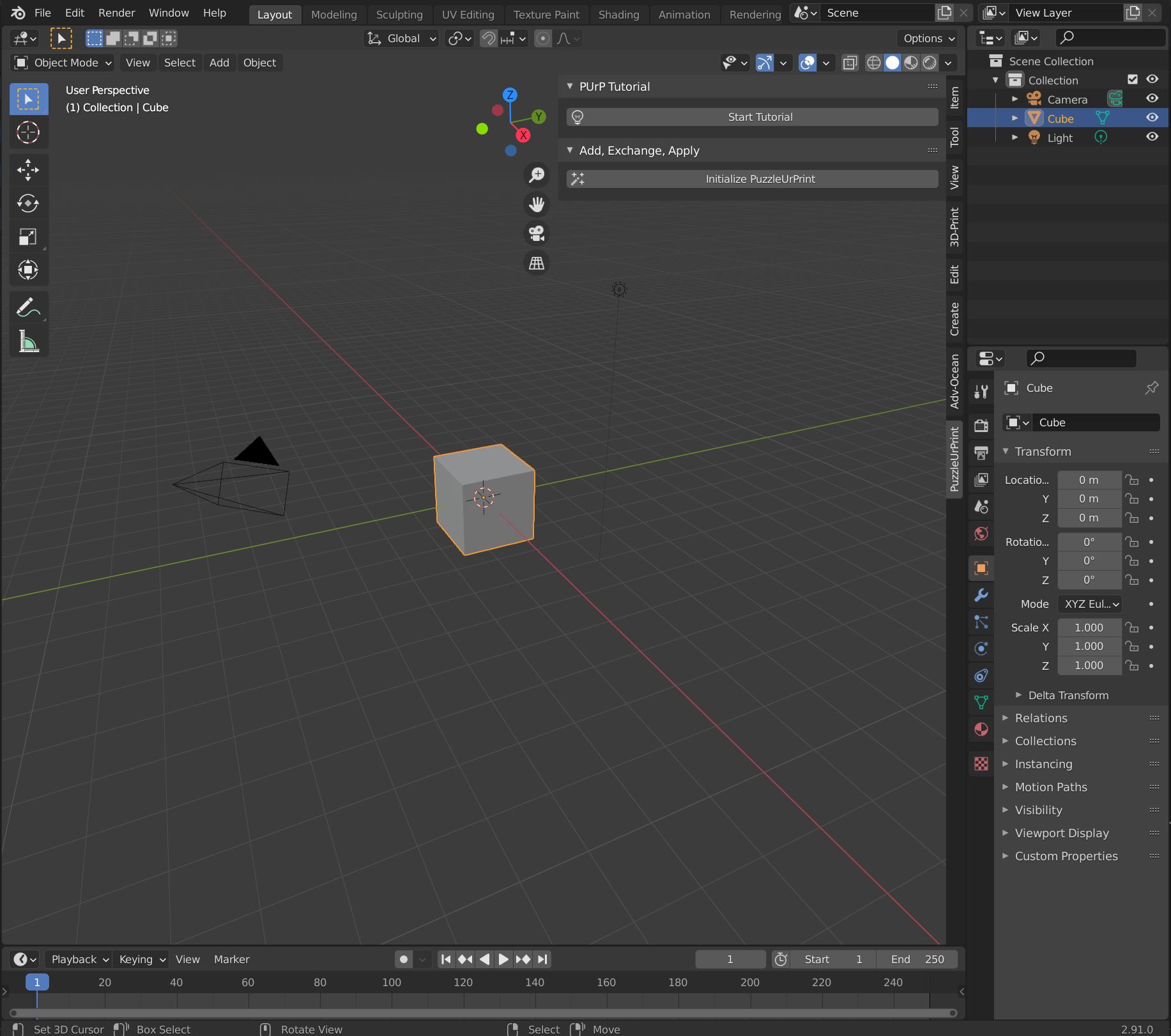
Before you can use the addon and see the settings you have to press the "Initalize PuzzleUrPrint"-button to get accesses to all options and the gizmos after each start of Blender. The Button can be found in the "PuzzleUrPrint"-panel in the 3DViewport on the right in the (n-)panel. You can also start the tutorial. This will also initialize the addon.
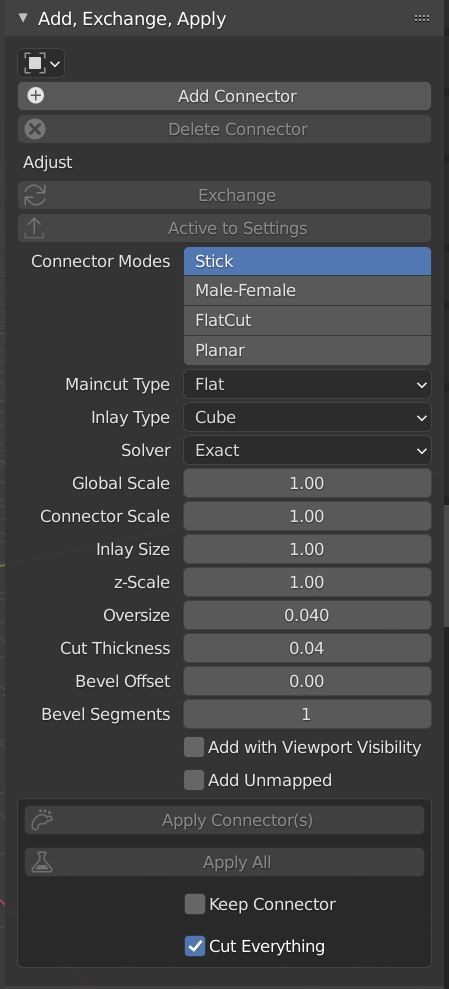
Add, Exchange, Apply
Centerobject
Allows to set the mesh object to which the next applied connector is mapped (if no other object is selected). Typically, this doesn't need to be touched. The "Add Connector"-operator will use this object only, if no other object is selected (except another connector).
Add Connector
Adds a new connector to the scene, mapped either to the selected mesh object or the object set as centerobj in the ui. The setting like Connector mode, type, scales..... for the new connectors are defined by the following options in the ui.
Delete Connector
Deletes all selected connectors including all modifiers and auxilary objects. Please use this option to delete a connector. Using Blenders own delete function will leave unselectable objects and orphan modifiers behind which will probably cause problems continuing working on the file.
Exchange
Applies the current settings in the ui to the selected connector(s). This allows to either finetune values in as numbers in the ui (rather than with the gizmos) and "exchange" the active with a new updated version. Together with "Active to Settings" exchange is like the paste option, which allows to paste the current settings onto the connector.
Active to Settings
This operator analyses the active (last selected) connector and sets its values in the ui. This way to can retain information of a connector when you already changed the settings to do something else. This acts also as the "copy"-option in many programms, where you save the data of one connector and use "Exchange" to paste them on to the another connector.
PUrP Settings
The following settings control the appearance of the next added connector as well as the appearance after exchanging a connector. These settings act as data storage were you can adjust settings, load configurations from existing connectors (Active to Settings-Button), or paste settings to connectors. However, changing these values in the addon panel will not instantanly change the appearance of the active connector. In order to instantly change the appearance of a connector, use the gizmo system. The gizmo system will automatically update the changed settings in the addon panel.
Connector Modes
Sets the Connector moode. Connector Modes include the 3 singleconnectors "Stick", "Male-Female", "FlatCut" as well as the multiconnector mode "Planar". See the section about the giz
Connector Type
Sets the connector type. Connector types are the basic underlying shape of the connector. "Stick" and "Male-Female" have Cube, Cylinder and Cone types which can be adjusted using the additional parameters. Planar connectors can have 16 different shapes including cubic, dovetail, puzzles, arrows, polygons, T-shapes and so on. For more information see the parts about the differenct connector modes and types.
Global Scale
All values in the addon are multiplied by the GlobalScale. The size of connectors, the oversize, the build volume, even the sensitivity of the gizmos. Typically, exporting formats like *.stl interpret size different to blender resulting in a need to scale up the models in the slicing software. Naturally, we start working in larger dimensions in Blender. Adjust the Globalscale to compensate. For example, a Globalscale of 10 allows to work nicely when blender meter translate to mm in reality (without scaling in the slicer or during blender export), which is the normal behavior of stl. When working with a Global Scale of 1 makes it necessary to scale objects after export by a factor of 10. However, it's the more typicall size range of "just starting a project in blender".
Connector Scale
The connector scale increases the overall size of a connector. In single connectors the mainplane as well as the inlay objects will be scaled all together. If you need extrem values for all connectors, consider using another globalscale.
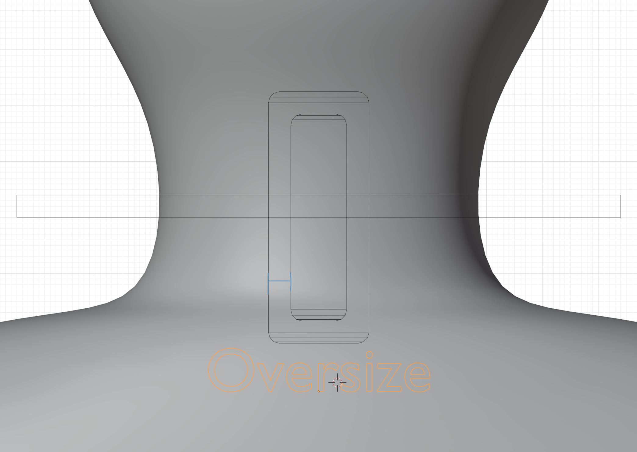
Oversize
The oversize value helps compensates for printer inaccuracies. All production methodes have an intrinsic error concerning the final size of the produced object. For example an FDM printer prints a small line of plastic along a specific path. If this path represents the intended outer wall, typically, a certain amount of plastic is deposited outside the path making the object a bit larger. For FDM 3d printing this value is typically around 0.03 cm, but depends on many values like nozzle size, print speed, curvature,... . The oversize setting will set the size difference between the inner and the outer (positiv and negativ) inlays of the single connectors or the thickness of planar connectors. This way a little gap is visible between the female and male parts of the connector. During printing this will be filled by the printer(error). The oversive is an absolut value. A larger print will have the same increase as a small print. Therefore it is important not so scale objects between applying the connector and printing. If you have no experience with the necessary values for you printer setup, make a few test prints to figure out the optimal value. Recommended starting values: 0.04 (0.4 nozzle), 0.06 (0.8 nozzle).
Inlay Size
Changes the size of the inlay (only single connectors)
z-Scale
Change the height of the inlay or the planar connector.
Cut Thickness
Change the Thicknee of the maincut. Keep it small but not zero. Maybe in the order of the oversize (only single connectors)Bevel Offset
Change the Bevel offset (length of the beveled part) of the inlay (only single connectors)
Bevel Segments
Change the number Bevel segments of the inlay. Higher values give a smoother bevel. Only visible when Bevel offset not zero (only single connectors)
Add with Viewport Visibility
When this check box is checked, the added or exchanged connectors will be added with the boolean modifier visibility on and you see a preview of the cut. Althoug, it might be nice to see the preview of the bool modifier already cutting a part, it makes working extremly slow. You can also toggle the visibility on/off by pressing 'Toggle Modifier Visibility' in the 'Mapping Order,Visibility'. To make it faster, you can also experiment to set the boolean type to fast.
Add Unmapped
Newly added connectors will unmapped.
Apply Connector(s)
Applys all selected connectors to there centerobject, the object will cut in half, and the connectors are added. When 'Cut everything' is checked then all object touched will be influenced.
Apply All
Applys All Connectors mapped to the selected centerobject(s). 'Cut everything' will make planar cut everything they touch, but will restrict single to cut only their centerobject.
Keep Connector
When this is checked, the connectors will not be deleted, but kept unmapped.
Cut everything
When checked, the especialy planar will not only cut there centerobject but everything they touch (important for consecutive apply of planar to the same object = Puzzle). A small difference exist in the behaviour Single Connectors when using the two apply methods: "Apply Connector(s)" will make Single Connecotors cut really everything they touch. However, the "Apply All" will make Single connectors Only cut there Centerobject.
Connector Modes
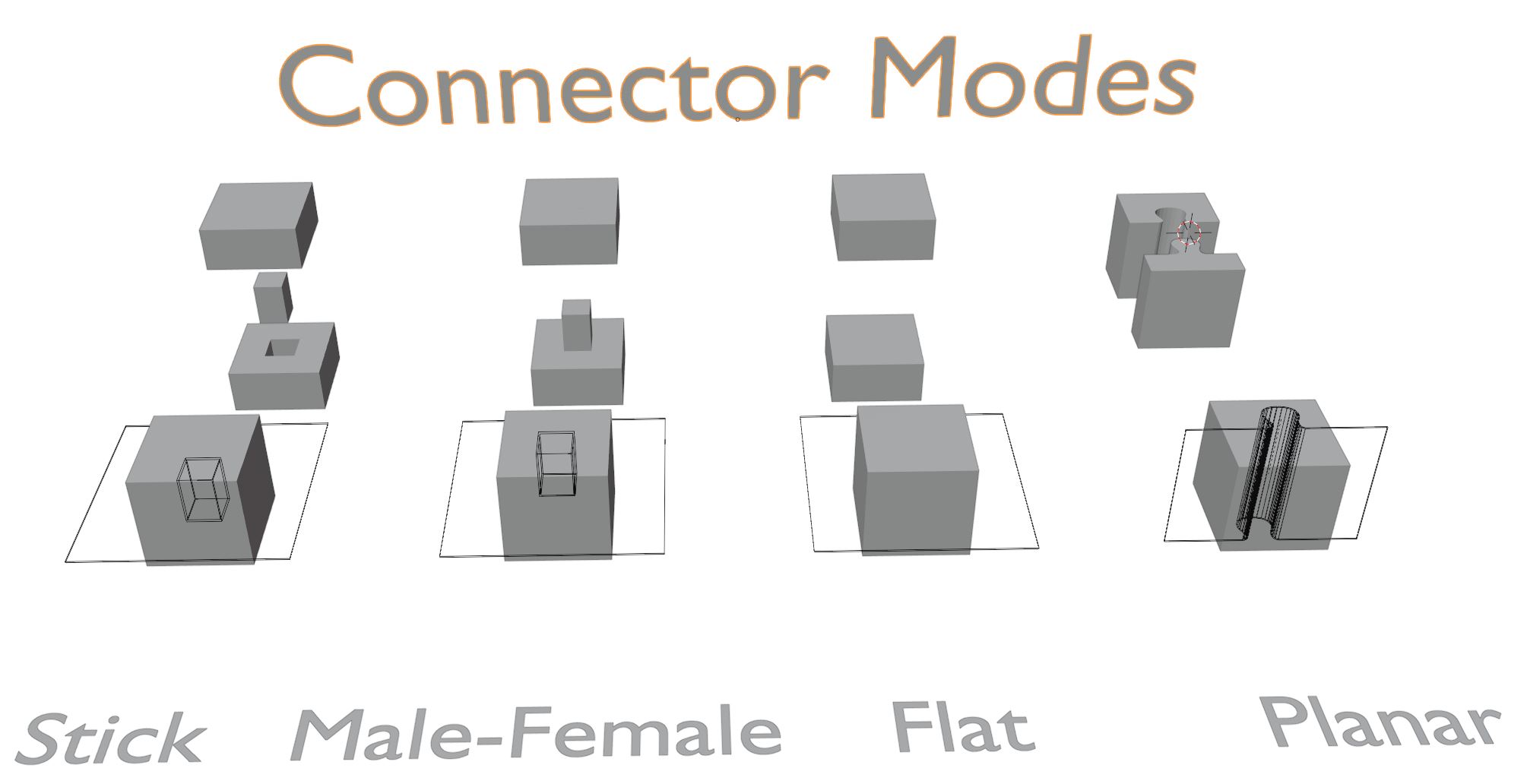
There are 4 types of connector modes.
- Stick
- Male-Female (mf)
- Flat
- Planar
Single Connectors
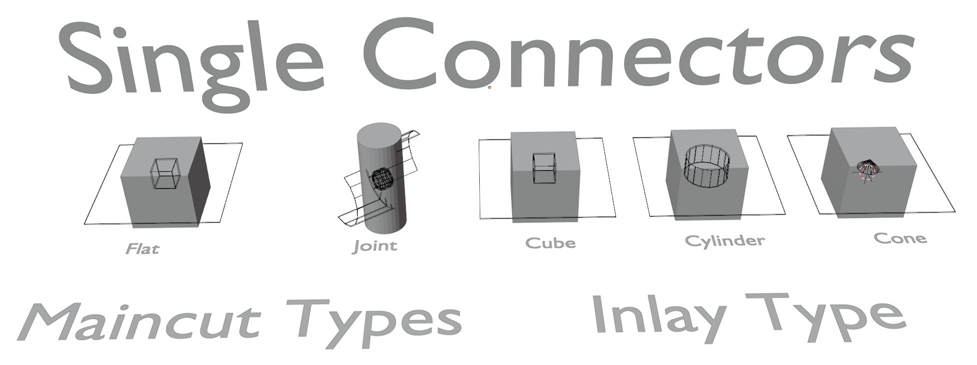
Single Connectors consist of one maincut and two inlay objects.%%The maincut causes the initial seperation of the object in two parts. You can choose the maincut type to be Flat or Joint. The Flat type is only a plane with a solidify modifier. It creates a flat base cut. However, the Joint type produces a circular ... joint cut (Please email me better terms) useful for example for elbows of your actionfigure. It is not forbiden to enter edit mode and change the shape to your liking. In most cases also 'Exchange' will not replace your adjusted maincut. %%The inlay shapes can be either cube, cylinder or cone. I forbid selecting them. Believe me, you'll mess it up. It's better for all of us. They are parented to the maincut anyway. Use the panel or the Gizmos to change them. Depending on the chosen Inlay Type additional settings might become available in the panel and gizmos. For example cylinders have additional settings to adjust the vertcount and radius, for cone you can set the upper and lower radius individually. However, also consider that some configuration will not make sense. For example a cone in stick configuration doesn't make much sense. However, all single connectors have a lot of parameters in common. Lets talk about them in the next part together with the gizmos system.%%%Useful Detail: You might get the error 'This connector didn't cut through'! Is this really what you want?'. Then you might Undo and check which Connector might need repositioning.
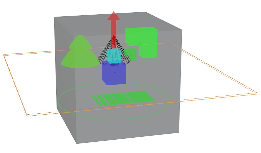
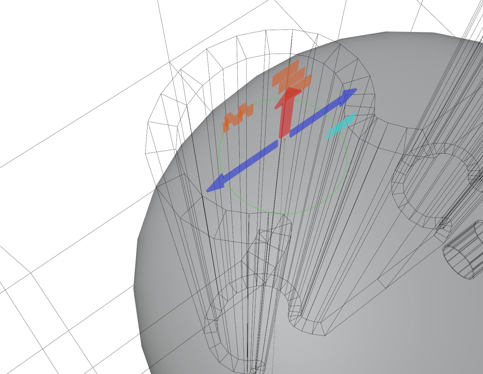
Single Connector Gizmos
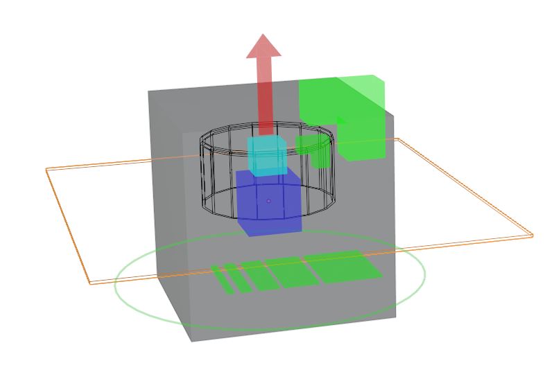
When you select a Connector several colorful symbols appear around the connecotor's origin (only avaiable when the addon is installed and initalized). These are controls to change several settings and, hence, the appearance of the connector. From bottom to top:
- - The two at the bottom control the maincut: the ring for the Connector Scale, the other for the Maincut Thickness (should be in the range of the oversize).
- The big blue cube controlls the Inlay Size
- the light blue controlls the oversize (see later!!)
- The Corner shapes represent controls over the Beveling, the large one is the Beveloffset and the small one the Bevelsegments (only visible when Beveloffset is not zero).
- The Red UP Arrow represents the zScale with which you can stretch the inlay along (local) z-axis.
- Cone type has additional two controls for upper and lower radius (import cone with radius top higher then 0 too have control over the top via gizmos)
Planar Connectors
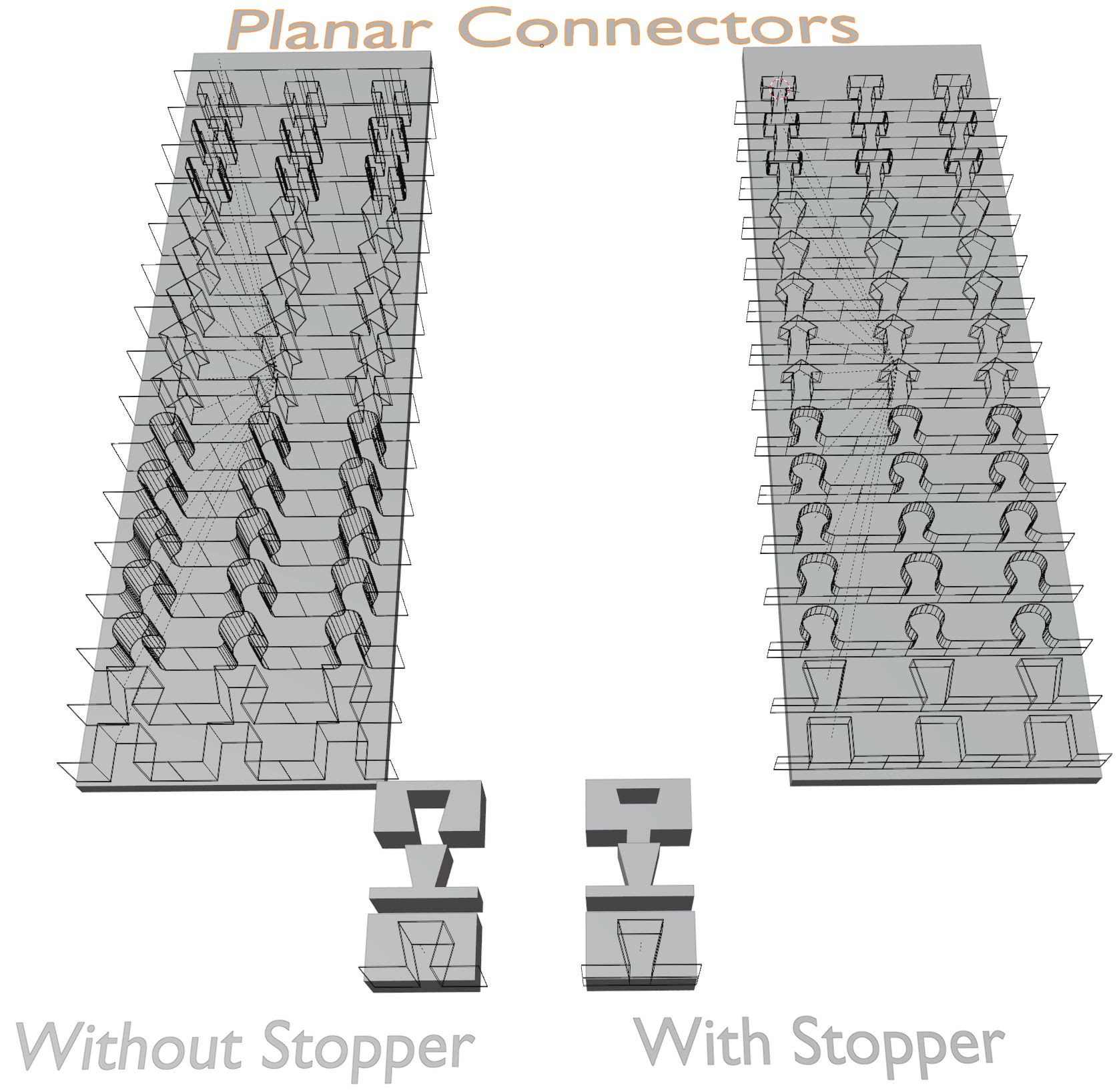
Planar connectors are essentially a plane with a coupling element and two array modifiers to duplicate it. In this version 16 different connector types (shapes) are avaiable: cubic, dovetail, different puzzle shapes, arrow, t-shape,... . Try out what fits for your project (recommendations for additional shapes welcome) One array duplicates allong the line, called Linelength. The other array generates copies of the original lines with Linecount being the number of lines and the Linedistance between those lines. Together with the Oversize, these 4 settings can be also changed via the 4 upper gizmos. You can keep the mouse on the gizmos to get small definition what it does. Additionally you'll find 3 Arrow shaped gizmos: the upwards arrow changes the zScale (height), the left and right arrows control the Left- and Right-Offset. This is the distance between the coupling element and the end of a repeating unit. Maybe reduce the 'Linelength' to 1 to get a clearer understanding of what they do.
A Subclass of Planar is called Planar with Stopper. In this configuration the Connector part ends somewhere in the middle of the plane and the rest is only a flat cut. Get one by activating the 'Stopper' checkbox and add or Exchange a connector. Models printed with this will not fall through like a puzzle piece but will be stopped at the right height when putting together. This is ideal for example to make wallmounts with replaceable parts, canvases, guitars,.... where ever you need the pieces slide into each other and stay where they are supposed to. When you have Stopper activated, you'll see the setting Stopper Height in the dropdown as well as in the connector's gizmos as a down arrow.
Positioning and Scaling
You can move and rotate the connectors as you like to find the right position using for example the typical Blender shortcuts 'r' and 'g'. Scaling with shortcut 's' is inadvisable because you change the scaling of the object. Better use the Connectorscale Gizmo (green large ring) for scaling. If it is more convenient for you to use 's' at least click the 'Connector Scale' - Gizmo once shortly after you are done. It will correct the scaling and will make the Oversize be consistent over all connectors. Again this oversize term. Next we'll get to it.
Oversize
The oversize setting allows you to compensate for printing inaccuracies.
We all know it: 3D printing is a wonderful thing but not really exact. Typically, a 3D printed part is a bit larger than it's supposed to be. For FDM (fuse depositon molding) printers, this comes for example from smearing material a bit over the side while following printing path. Also the shape of an object and as a result the path the printer takes, will have an influence on the oversize. Try printing two walls connected in a 90° angle. Especially, with high printing velocities you'll see thickening at the outside of the corner. Of course, also nozzle size, problems with overhanging parts, brim, orientation of the part... the number of influencing parameters is large, so it is unfortunately hard to give a perfect recommendation for all cases. However, the oversize is the option to compensate for all those parameters. Keep in mind, that the oversize is an absolute value. If the printer's oversize 0.4 mm for a small object, your print has the same oversize for a bigger object. On the one hand this means the connector can have the same oversize despite their size. On the other hand your PUrP Oversize might get wrong when scaling object later (e.g. in the slicer software).%% Useful Detail: My Oversize Values - Fortunately, I found a very consistent picture for my system (Cura+Ultimaker3) where I can use an Oversize of 0.02 for all round shapes (cylinder, cone, puzzles,...) for a tight fit even independent of the nozzle size. Only cube inlays need 0.03 for a nice fit. But I really recommend printing small test pieces with different oversize values until you figure out the best values for your 3D Printer.
Mapping
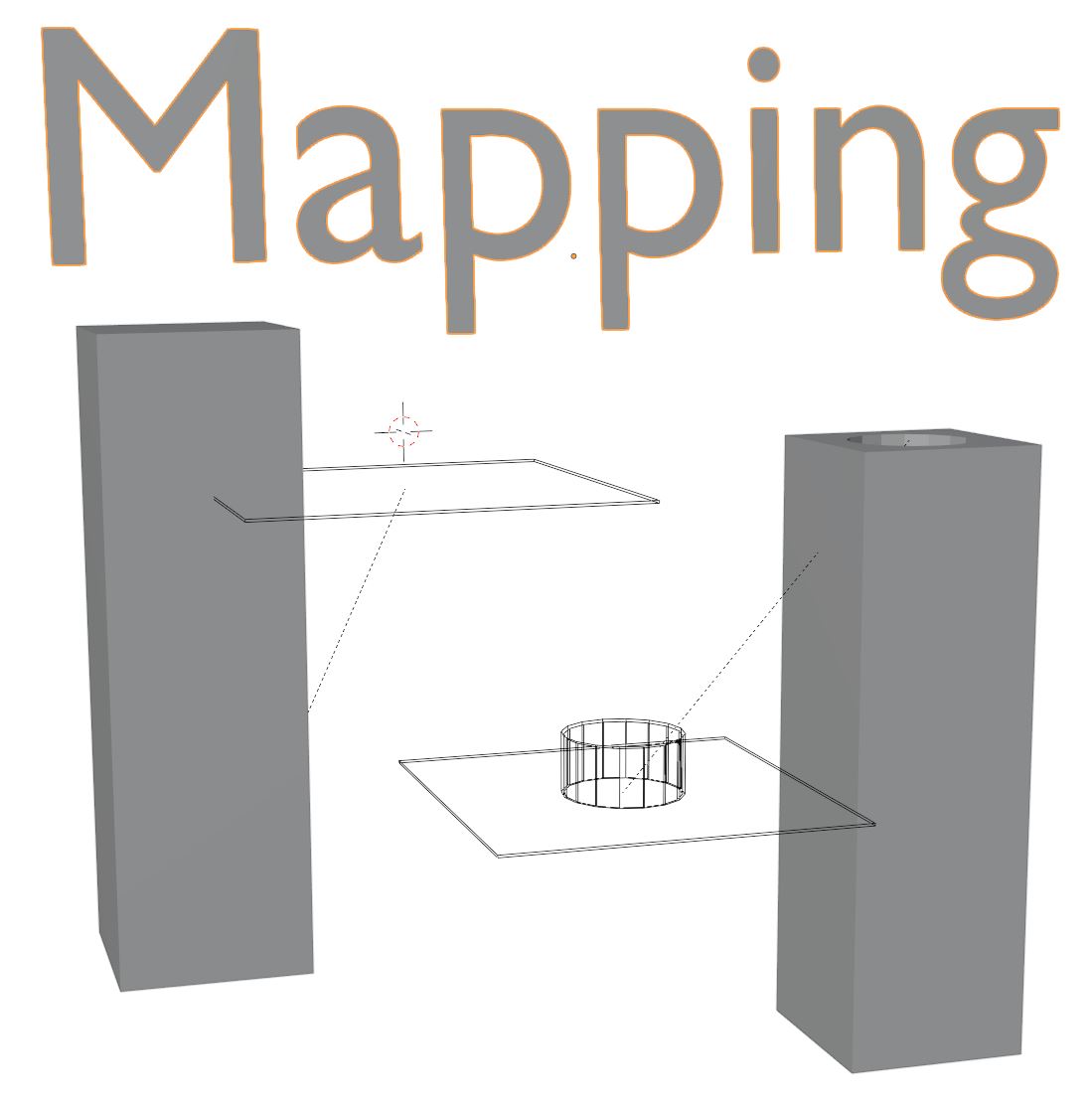
Mapping is the way connectors are bound to the object they are supposed to cut (Centerobject). It includes parenting. When you move the object in the viewport the connectors will follow. Moreover, mapping also includes having the boolean modifiers of a connector already on the Centerobject allowing you to preview the result (if you can work with a slow blender). The addon will check for these attributes during applying. A Connector can only be mapped to one Centerobject% However, you can change the mapping of a connector by using the 'Remap Connector to Active'-Button. Select the connector you want to remap and then the new Centerobject it should be mapped to and press the 'Remap Connector to Active'-Button. Now the parenting and the modifiers exist on the other object. Moreover, if you don't want to have a connector mapped to any object, you can either add them with the checkbox 'Add Unmapped' in the 'Add, Exchange,...'- dropdown enabled or you select an existing connector and press 'Unmap Connector' in the 'Mapping, Order, Visibility' -dropdown.
Useful Detail: If a mapped connector doesn't touch/cut any part of a Centerobject during applying (for example Apply All), it will remain in the scene and will be labeled unmapped. If you get this during applying when you don't expect it, check if your connector is not secretly touching another object (maybe an object that will exist after cutting everything in pieces).
Applying and Order
By Applying a Connector you finalize the editing process, cut the model in pieces and add the connectors. You can choose to select one or several connectors and Press 'Apply Connector(s)' to have only specific connectors applied or you press 'Apply All' (both in 'Add,Exchange,Apply'-dropdown) to apply all Connectors mapped to a Centerobject (or the Centerobj the selected Connector is mapped to). When the checkbox 'Cut Everything' is disabled, the connectors will only cut the objects they are mapped to. For several planar connectors this will mean that not all resulting objects get cut by the following connector. Enable 'Cut Everything' to have the connecotrs cut everything they touch.
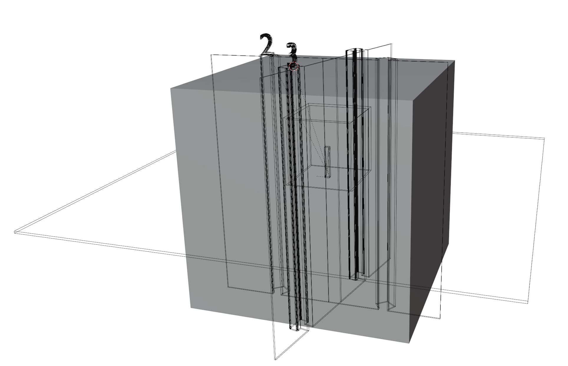
The order in which the Connectors are applied can be displayed as little numbers above the Connectors by toggling on/off with 'Toggle Order' in the 'Mapping,Order,Visibility'-dropdown. The order can be changed by selecting a connector and pressing either 'Up in Order' or 'Down in Order'. Monitoring the order is rarely necessary but in an example like this it can be important.
By default the connectors get deleted after applying. If they are precious to you check the checkbox 'Keep Connector' before applying and they will be kept unmapped.
Mapping, Order, Visibility - Menu
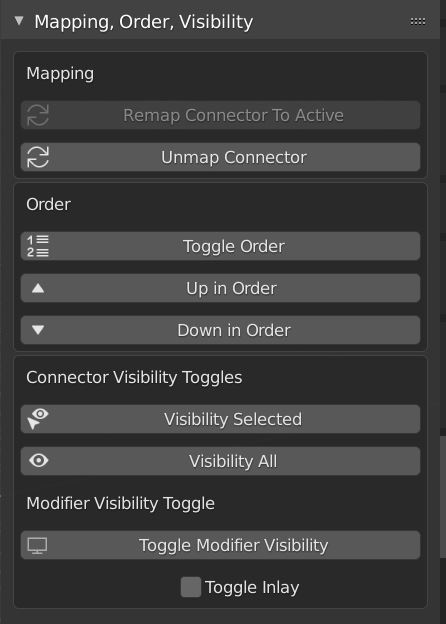
The Mapping, Order, Visibility - dropdown is seperated in two the 3 segments mentioned in the name.
Mapping:
- 'Remap Connector to Active' will change the mapping of the selected connector to the active (last selected) object.
- 'Unmap Connector' removes all dependencies of the selected connector(s). It will be marked as unmapped and ignored in all apply processes. It's definetly way a fast way of working to work with unmapped connectors, but don't forget to map them eventually.
Order
- 'Toggle Order' shows the order of all connectors mapped to a certain object
- 'Up in Order' moves the selected connector up in order. Hence, it will be applied earlier.
- 'Down in Order' moves the selected connector down in order. Hence, it will be applied later.
Modifier Visibility (preview of cut)
- 'Toggle Modifier Visibility' toggles the boolean modifier visibility and shows the preview of the cut. Will make working slow.
- 'Toggle Inlay' check box controls whether the 'Toggle Modifier Visibility' also toggles the visibility of the inlays of single connectors
Special Apply Menu
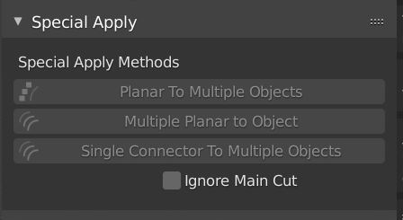
The 'Special Apply'-dropdown has some extra operations that might get helpful:
- 'Planar To Multiple Objects' allows you to decide which objects also should be cut through in addition to the Centerobject the planar is mapped to. For example (left) you make a puzzle and applied only the first planar, the second will be only applied to the one row its mapped to. Select all rows first and select the remaining planar last. Then Press Planar To Multiple Objects'. BTW: 'Apply All' will do this automatically.
- 'Multiple Planar to Object' does it the other way around. Select several Planar Connectors, select the Centerobj of choice last and press the button. Typically 'Apply All' handles these cases reliably. However, this can become useful if you can't use 'Apply All'.
- 'Single To Multiple Objects' This allows you to connect one Single Connector being applied to several Objects. Imagine your character needs a new hat. Select the hat and the character and the Single Connector last and press 'Single To Multiple Objects'. You can also enable 'Ignore Main Cut' to do exactly that during applying.
BuildVolume
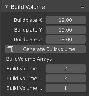
Especially when you dissect large objects to fit in your 3D printer, you always need to know how big your print real estate is at all times. In the 'Build Volume'-Dropdown, you can set the size of your 3D printer in cm (probably if you haven't changed it globally to freedom units) and press 'Generate Buildvolume' to get this cube (set to wireframe). When added you can adjust also its repetition in x,y and z. You can add as many as you like. The settings will only be available for the last selected Build Volume. The BuildVolumes are nothing more than simple objects to get a feel for the available space. Otherwise they do nothing.
Typical Process
Here is a typical workflow to work with the addon:
- 1. Import/append model, apply all modifiers (keep backup)
- 2. Select the model
- 3. Set the 3d cursor to a point where you want to add a connector. Press Add Connector
- 4. Adjust settings, exchange, position with 's' and 'r'-shortcuts, fine tune with the gizmos...
- 5. Repeat to add more connectors as you like, use 'Active to Setting' and 'Exchange' as copy and paste of connector settings.
- [6-53]. ...
- 54. Maybe print a few test cuts to figure out the best oversize value and adjust the connectors accordingly.
- 55. Adjust all Oversize values according to your test results
- 56. Apply All Connectors or do it manually one by one
- 57. 3D Print
- 58. PUZZLE THEM TOGETHER
- Please send me pics, models and suggestions to info@modicolitor.com
Things to looks for and Trouble Shooting
Before I let you go explore more on your own here are some things to keep in mind to have everything working nicely as intended:
- The objects you are using must be manifold (water tight). A single plane will not work. It needs thickness. Also enable the 3D Printing addon shipped with blender. It allows to check 'how manifold' (and pregnant) your object is and often repairs it (not the pregnancy).
- The addon is strongly reliant on blender's boolean modifier. With the 2.91 update the exact solver arrived and the number of fails drastically decreased. However, sometimes the boolean modifier just produce s***. In these cases increasing or reducing resolution and repositioning might help.
- Some Planar types produce problems with too large oversize values due to self intersection. The Exact solver will often completly delete the object during applying. Changing the solver to "Fast" will maybe solve this problem. However,the bad geometrie will still be transfered to your model during applying and may cause problmes during printing
- All other modifiers must be applied before starting to apply the Connector. Keep in mind the addon ignores all modifiers that it hasn't created itself. When you have a large stack of modifiers before (or just one) before you start cutting, the preview before and the result after applying the connector will look not as expected.
- Always also consider the orientation during printing. Overhangs are always a problem in fdm printing. In addition, also the x-y-resolution is different than in z-direction. Good cut design can lead to less overhangs and better results. However, the oversize might change when the orientation during printing changes (seen in rare cases where it needs to be really precise).
- I guess it's obvious, but let me make sure everyone understands: we are cuttings things in pieces with this addon. If this model is the only version you have and you save the cut model over the only original, that's it! The model is gone. The addon does not make any safety copies. Please keep your head together. :-)
- Have Fun and create great things!!!